 Application Note
Radome Thermal Insulation
 |
 |
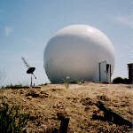 |
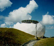
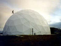
AFC manufactures four types of dielectric radomes. The four types identify themselves primarily by the radome wall construction. In each case, the dielectric panel edges are reinforced into flanges for adjacent panel assembly. The dielectric flanges form a framework known as a Dielectric Space Frame (DSF). Depending on radome wall parameters, adjacent panel flanges may also serve as environmental load bearing beams or struts. Each panel is a molded one piece unit. When assembled to the other panels, the panel array forms a truncated spherical surface. Individual panels may be doubly curved or flat yielding a faceted or spherically smooth appearance. Foam insulation is often added to the wall producing a two or three layer sandwich configuration. As required by sophisticated electrical performance requirements, inductive elements (wire, metallic strips etc.) may be laminated into the dielectric flanges to reduce scattering loss by using a process known as impedance matching.
The four DSF radome types are:
- The thin wall DSF radome where adjacent panel flanges carry all the environmental loads. Wall thickness is usually 0.040 inch or less.
- The solid laminate wall DSF radome. Wall thickness is typically 0.090 inch.
- Adding a layer of foam to the inside thin wall DSF radome forms a two layer sandwich. Foam thickness is chosen primarily for thermal insulation and cost objectives.
- The composite sandwich foam core wall radome. Core thickness is chosen as 1/4 wavelength for the highest RF signal frequency. For a given radome diameter, the sandwich foam core radome is the most expensive version.
 The two and three multilayer wall radomes normally have significant insulation value differences. When operating under extreme weather conditions, such differences need to be understood in characterizing radome heating and/or cooling requirements. While the two layer wall radome structural parameters supporting environmental wind loads and RF performance are independent of the foam thickness, the three layer version, on the other hand, is not. With the three layer sandwich, core thickness is determined by antenna system frequency. The higher the frequency, the thinner the core thermal insulation value.
In order to detail the insulation value of the two and three layer wall radomes, the above two graphs characterize the amount of heat necessary to raise the internal radome temperature 50 degree C.
 The two layer wall heat requirement is calculated for 0.5 and 2 inch foam insulation thickness for radome diameter from 12 to 48 foot diameter. In contrast, the three layer foam core sandwich radome heat requirement is displayed for a 18 foot and 31 foot diameter radome with operating frequency determining the final core thickness value.
In choosing a radome type, the three layer sandwich radome is optimized for RF performance and, for the most part, has better RF performance over its two layer wall counterpart. Broad RF frequency bandwidth is characteristic of the two layer wall radome with foam thickness optimized for thermal insulation constraints. To enhance RF performance, impedance matching may be applied to both radome types.
The thin membrane wall dielectric radome is often a preferred choice when cost becomes an issue. At the same time, this type radome is often deployed where air-conditioning or heating is considered a must (for example the hot, moist salt laden climate of a Pacific Ocean island.) Under such circumstances, one can trade-off air-conditioning or heating operating efficiency for the fixed radome cost. An example of the trade-off is shown in the table below for a 52-ft. diameter thin membrane wall dielectric radome and a 2-layer sandwich wall radome.
|
Assumption 2 KW Internal Heat Generation with Sun Load 400 Btu/Hr*ft2 |
2-Layer Sandwich Wall Radome |
Thin Membrane Wall Radome |
|
Cooling for 50-degree F temperature reduction. |
55,000 Btu/Hr |
460,000 Btu/Hr |
|
Cooling for 25-degree F temperature reduction. |
39,000 Btu/Hr |
300,000 Btu/Hr |
From the table, the 2-layer sandwich wall can provide an 8-fold reduction in the capacity of the air-conditioner that would be required for effective climate control within the radome. Should climate control be part of the 20-year life-cycle solution, the 2-layer sandwich wall upgrade significantly reduces the operational power costs.
Note that all dielectric radome types often serve similar applications. Application specific necessities typically emphasize RF, environmental or cost concerns. These concerns then dictate radome type and in the final analysis, radome price.
AFC manufactures, markets and sells worldwide satellite dish antennas, conical horn antennas, radomes, antenna feeds, microwave and waveguide components, ultra low loss waveguide transmission line Tallguide®, and shelters. Our customers serve the broadcast, communications, radar, weather and cable industry, defense, government, and government agencies worldwide.
A complete Internet WWW AFC document index may be found in Antennas for Communications (AFC) Home Page Document Summary List. Additional radome information is contained in AFC's Radome Capability.