
Transportable Antennas
2.4, 3, 3.66 and 5 meter for C, Ku and Special Band Operation
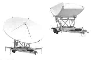 AFC's transportable antennas offer superior performance for a variety of different applications. The antennas may be used for uplinks or downlinks in the C, Ku or other bands of operation. In the C band the uplink frequency is 6 GHz, the downlink frequency is 4 GHz. In the Ku band the uplink and downlink frequencies are 14 and 12 GHz, respectively.
 The antennas consist of a composite material fiberglass reflector mounted on an elevation over azimuth base. The azimuth base provides 360° rotation, the elevation is continually adjustable over a 55 degree range from 5 to 90 degrees. In the US, the range is set from 10 to 65 degrees.
The 2.4, 3 and 3.66 meter antennas may be operated with wind gusts of up to 60 mph; the 5 meter antenna is rated for wind gusts of up to 40 mph in the standard configuration.
Depending on reflector size, the antenna base is mounted on a single or dual axle, 8 foot wide trailer with a standard ball hitch. The trailer is equipped with three, crank operated feet for leveling and stability. On the 5 meter antenna the top and bottom portions of the reflector are hinged to fold back to the center of the reflector during transit. The maximum recommended towing speed is 55 mph.
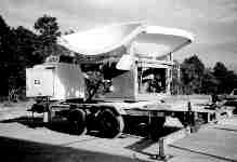
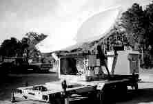
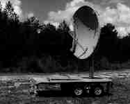
Transportable antennas are manufactured with many and various options. Options include foldable 3 piece reflectors for 2.4, 3, 3.7 and 5 meters diameter quick deployable missions, shelters, anti-ice, feed systems, hand-crank or motorized Az/El pedestals. The table, below, shows AFC's transportable antenna operating specifications.
 |
 |
 |
| Electrical | ||||
| Frequency | ||||
| Downlink | C-band 3.7 to 4.2 Ghz or Ku-band 11.7 to 12.2Ghz | |||
| Uplink | C-band 5.9 to 6.4 Ghz or Ku-band 14.0 to 14.5 Ghz | |||
| Midband Gain dB | 2.4 meter | 3.0 meter | 3.7 meter | 5.0 meter |
| 4 Ghz (WR229) | 37.7 | 39.5 | 41.0 | 44.0 |
| 6 Ghz (WR137) | 41.2 | 43.3 | 44.8 | 47.8 |
| 12 Ghz (WR75) | 47.3 | 49.0 | 50.7 | 53.5 |
| 14 Ghz (WR75) | 48.6 | 50.5 | 52.0 | 55.0 |
| Beamwidth (degrees) | ||||
| 4 Ghz | 2.14 | 1.75 | 1.40 | 1.10 |
| 6 Ghz | 1.43 | 1.10 | 0.92 | 0.68 |
| 12 Ghz | 0.71 | 0.59 | 0.48 | 0.35 |
| 14 Ghz | 0.60 | 0.49 | 0.40 | 0.29 |
| Maximum VSWR | 1.3:1 | |||
| Input Flange | CPR-229 (4 Ghz), CPR-137 (6 Ghz), WR75C (12 and 14 Ghz) | |||
| Sidelobes | FCC requirements for 2 degree satellite spacing | |||
| Polarization Adjustment | 360 degrees by rotating feed | |||
| Noise Temperature vs. Elevation Angle | 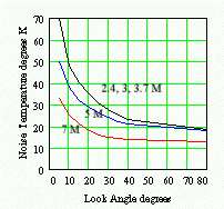 |
|||
| Mechanical | ||||
| Reflector Sections | 1-piece for 2.4, 3 and 3.7 meter, 3-piece foldable for 5 meter. Optional 3-piece foldable for 2.4, 3 and 3.7 meter. |
|||
| Temperature Range | -60o F to +125o F (-51o C to +52o C) | |||
| Mount Type | Fixed pointing elevation over azimuth, rotatable 360o. Optional hand-crank or motorized pedestal. |
|||
| Material | ||||
| Reflector | Composite fiberglass | |||
| Backup Structure | Composite reinforced fiberglass or aluminum | |||
| Feed | Aluminum | |||
| Mount | Hot dip galvanized steel | |||
| Equipment Included | For 2.4, 3 and 3.7 meter -- dual polarity RO linear feed, elevation jack. For 5 meter -- dual polarity RO feed, 2 spud wrenches, 2-ton cable winch, 2 elevation jacks. |
|||
| 2.4 meter | 3.0 meter | 3.7 meter | 5.0 meter | |
| Trailer Dimensions | 15' 2" long, 8" wide, single axle, 150 lb. tongue weight, 1.5" hitch ball required, hot-dip galvanized. | 18' 2" long, 8' wide, double axle, 200 lb. tongue weight, 2" hitch ball required, hot dip galvanized. | 21' 2" long, 8' wide, double axle, I-beam construction, single-axle surge brakes, 400 lb. tongue weight, 2" hitch ball required, hot dip galvanized. | |
| Net Weight | 1200 lb. (545 kg) | 1610 lb. (730 kg) | 1913 lb. (868 kg) | 3741 lb. (1697 kg) |
| Maximum Height | 10 ft. 3 in. (3.1 m) | 11 ft. 3 in. (3.4 m) | 12 ft. 3 in. (3.7 m) | 12 ft. 6 in. (3.8 m) |
| Options | Tx/Rx or CP feeds, embedded wire self regulating anti-ice system, hand-crank or motorized pedestal, equipment shelters. |
|||
| Specifications Subject to Change | ||||
AFC manufactures, markets and sells worldwide satellite dish antennas, conical horn antennas, radomes, antenna feeds, microwave and waveguide components, ultra low loss waveguide transmission line Tallguide ®, and shelters. Our customers serve the broadcast, communications, radar, weather and cable industry, defense, government, and government agencies worldwide.
A site index of other AFC WWW documents related to antennas and AFC products may be found in Antennas for Communications (AFC) Home Page Document Summary List.
Top of PageReturn to AFC Home Page

AFC Page Browser
Telephone (352) 687-4121 Fax (352) 687-1203 E-mail sales@afcsat.com
Tallguide is a Registered Trademark of Antennas for Communications
Copyright © 1996 - 2001 Antennas for Communications