 Multi-Satellite Feed System
for 2-Degree Satellite Spacing
by Thomas G. Hill and Bob G. Haney, Sammons Communications, Inc. and
Tore N. Anderson, Steve Galagan and Dr. Ronald S. Posner
Antennas for Communications
Reprinted from CED Magazine April 1992

Return to AFC Home Page Return to AFC Profile
Introduction
 |
 |
Several years ago, cable operators observed with considerable interest plans to move two major cable satellites to a three-degree orbit spacing. Now, a few years later, operators are contemplating the ramifications of several satellites being spaced just two degrees apart.
By the middle of 1993, virtually all cable systems in the continental United States will have to have the capability of picking up a minimum of five satellites, plus others being used for regional sports, pay-per-view and other special events. Four of the satellites that many cable systems will be using are to be lined up with 2-degree spacing from 131 degrees to 137 degrees (see Figure 1).
| Orbital Position | Satellite Designation |
| 137 degrees | Satcom C1 |
| 135 degrees | Satcom C4 (F4R replacement) |
| 133 degrees | Galaxy G1 |
| 131 degrees | Satcom C3 (F1R replacement) |
| 125 degrees | Galaxy G5 |
| 93.5 degrees | Galaxy G3 |
Due to space limitations caused by surrounding trees, buildings and low elevation angles found in the northeastern part of the United States, many earth station headend sites have severe restrictions on the satellite viewing arc. As more and more satellites come on line, the earth station space crunch at the headends has come to the point where many headends simply do not have any more room to add even just one more dish.
Space crunch solutions
There are alternative solutions to the space crunch problem: buy or lease additional adjacent property or move the headend. Both options are expensive, even if the cable operator could find suitable property and satisfy all of the local zoning requirements. A better solution is to create more value from current antenna space resources by finding a way to pick up multiple satellites with existing antennas. Many cable systems have one or more 4.5- to 7-meter antennas already in use, which are ideal for retrofitting to a multi-satellite feed (MSF) system.
While MSF systems have been explored since the 3-degree satellite orbital move, a 2-degree solution has evaded an engineering solution. Mechanical constraints alone pose nearly an insurmountable problem. Feed scalar plates overlap. Horizontal and vertical orthomode couplers, low noise amplifiers or block converters interfere as they compete for the same space.
Brute force won't work
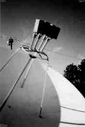
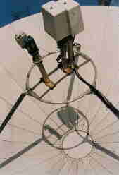
 Brute force attempts to literally bend feed assemblies away from the same interference volume have led to feeds with large, 3-dB to 10-dB power suckouts (see Figure 2). The power suckouts appear randomly over the entire C-Band (3.7 GHz to 4.2 GHz frequency range). To make matters even more complicated, the power suck-outs are accompanied by random polarization twists of horizontal and vertical transponders. Often no orthomode cross-polarization nulls are measured or a pea soup chaotic mixture of polarized signals are encountered over the band.
This article investigates the criterion for activating higher order waveguide/feed modes, which suck-out satellite energy and examines the significance of bending the feed pipe (variation of propagation direction) in destroying polarization purity.
The Antennas for Communications (AFC) MSF 2-degree satellite feed extension is proposed along with expected antenna performance. Measured MSF results are reported on the Sammons Communications 5-meter Scientific-Atlanta dish located at Newport, Tenn.
Higher order waveguide/feed modes
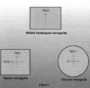 Ordinary rectangular waveguide, such as WR229 for 4 GHz operation, will not support microwave energy in two polarizations as required for "Frequency Reuse Satellite Systems." To solve the two polarization obstacle, it becomes necessary to go to either square or circular waveguide. (See Figure 3)
Microwave energy, propagating in rectangular or circular tubes, have electromagnetic field patterns which depend on frequency and waveguide shape. The lowest frequency mode is called the fundamental mode. Other modes, which begin to carry energy at higher frequencies, are termed "higher order" modes. As is often the case, several higher-order modes often turn up over a frequency band along with the fundamental waveguide mode. In general, larger waveguide dimensions promote lower frequencies for higher-order mode propagation.
Square waveguide is difficult to build and design feed structures for parabolic dishes. Circular waveguide, on the other hand, lends itself naturally to feed design, providing optimum performance and supporting continuous polarization rotation adjustment. Circular waveguide, however, has a much reduced frequency range for mode free operation in the fundamental TE11 mode. Also, any change in waveguide diameter acts as a higher-order mode converter.
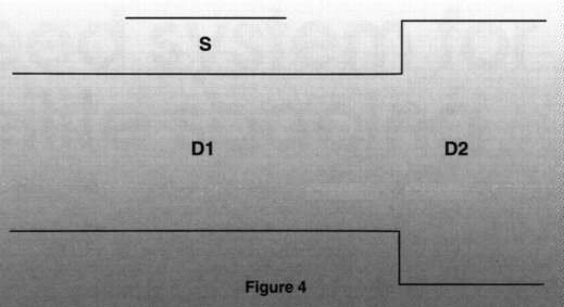
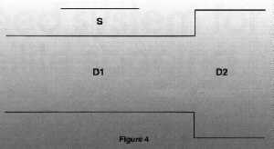 Indeed, signal energy is transferred out of the fundamental mode into the higher-order modes. The most important higher-order mode is the TM01. For an abrupt diameter change, energy is coupled into the TM01 mode at a rate (4S/D1)2. (See Figure 4)
From a feed designer's point of view, multi-mode operation is very desirable. A larger diameter is required to impedance match the circular waveguide to free space over the 3.7- to 4.2 GHz frequency band. More too, the correct amount of TM01 and TE11 energy will better shape the primary feed radiation pattern to optimize the dish far field antenna radiation pattern (achieve high gain and low sidelobe level).
For 2-degree satellites, it is necessary to space the feeds closer together. Mechanically, the simplest way to perform this task is bend circular waveguide to a shape where the orthomode junctions no longer interfere with each other. Mounting the existing feed and scalar plate directly against the bent circular waveguide, however, causes two problems for "Frequency Reuse" crosspolarized signals.
Circular waveguide is continuously symmetric over 360 degrees. What this means is that circular waveguide may be rotated around any axial angle without any change in shape. Without any means of identifying specific direction, circular waveguide modes may be polarized at any rotation angle. When circular waveguide is bent though, the complications really start. For one signal polarization, the bend lies in the magnetic field plane.
For the other polarization at 90 degrees, the bend lies in the electric field plane. For most bend configurations, the actual signal polarization is some crazy combination of the two. These opposite polarizations, as they traverse the bend, have different phase velocities. They result in an elliptical polarized wave, seriously impairing cross polarization discrimination and increasing adjacent channel interference. Further aggravating the problem, the elliptical polarization rotates continuously over the frequency band guaranteeing no unique polarization solution.
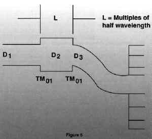 The second problem again arises from clamping an oversized feed, scalar plate assembly directly against the bent circular waveguide. At certain frequencies, a resonant cavity is formed, where the trapped TM01 mode is exactly a multiple of a half wavelength long. The trapped TM01 energy bounces back and forth causing suck-outs at these resonant frequencies as well as introducing time and phase delay distortion.
Suck-outs as large as 20 dB have been measured at certain frequencies within the 3.7- to 4.2-GHz band. Between resonant frequencies, good fortune sometimes admits reasonable carrier-to-noise ratios on some transponders but other adjacent ones disappear into the noise level. These same between frequencies have a VSWR of 1.9 to 1(-10 dB return loss). Thus VSWR increases transmission loss by 0.5 dB and noise temperature by 29 degrees K. For a 80-degree K LNA/LNB, the antenna system performance is degraded by another 1.5 dB.
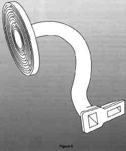
In all cases, the action of circular waveguide bends on dual-polarized signals is serious crosspol interference (see Figure 5). As those who have worked on telephone network microwave repeater link installations know, circular waveguide is frequently used to reduce transmission line loss. During installation, the circular waveguide is very carefully and precisely aligned in a straight line to avoid the slightest hint of misdirection. Bends in circular waveguide have big consequences.
Mimicking the communications industry, the best feed approach for 2-degree satellite operation is to use a straight, "spurious free" high-performance extension. The extension length is chosen to simultaneously remove the orthomode junction interference conflict, maintain the higher-order TM01 to TE11 mode ratio and preserve the phase relationships between these same modes.
Multi-sat antenna scanning
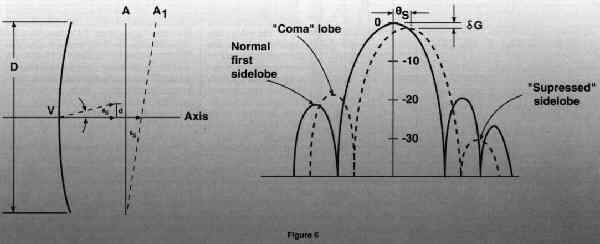
When the feed of a parabolic antenna is displaced at an offset angle from the focal point, the main beam of the radiation pattern moves in the opposite direction. For practical antenna parameters, the main beam scanning angle is nearly equal to the feed offset angle.
|
| MSF Gain Loss vs. Scan Angle. |
Practically speaking, the scanning process can continue until the gain loss and comma lobe interference produces objectionable results. One of the authors has experimented with scan angles as large as 10 degrees with acceptable picture quality. Other higher order aberrations, such as astigmatism, filling in of pattern nulls and beam broadening, are associated with large scan angles.
For 2-degree spaced satellites, scan angle are confined to a narrow +8-degree or less range. Over this range the decrease is gain can be approximated by:
Experimental results
|
|
Adjusting the feeds for optimum polarization on this system was virtually impossible. The AFC feed, on the other hand, exhibited a more linear frequency response and allowed precise polarization nulls.
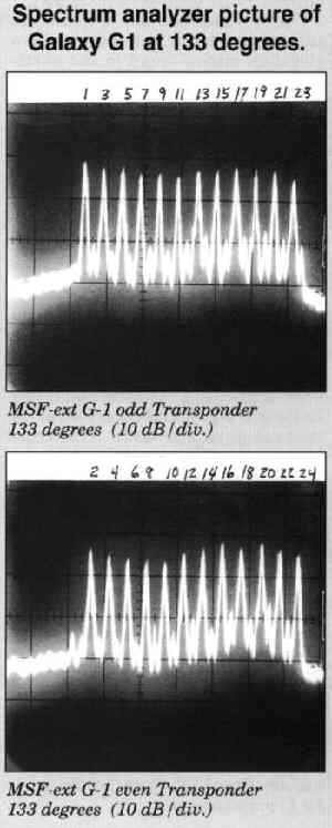
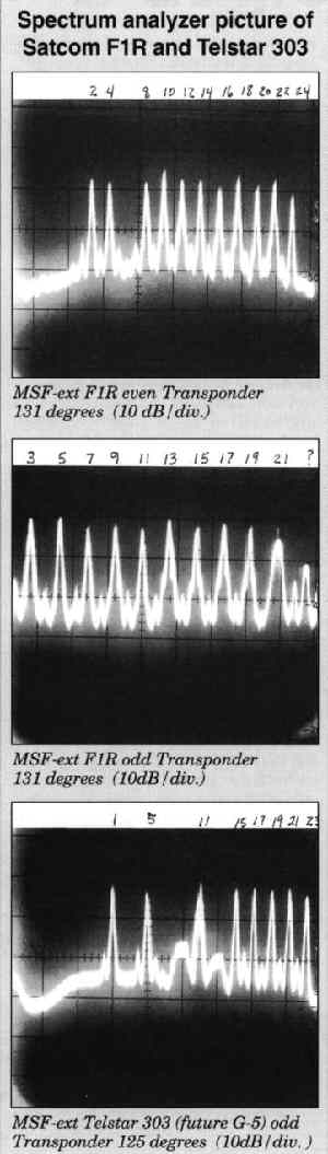
The Sammons' field test was laid out to determine expected performance on existing satellites located around 133 degrees over to where Galaxy G5 will be positioned at 125 degrees. Consequently, three feed extensions were installed to receive the three satellites:
|
Indications are that the MSF-16 is capable of looking at as many as seven satellites spaced 2 degrees apart. The five feed positions set in the middle would have losses (over a single feed) of 0 to 0.5 dB. It appears that the two end feeds would have losses of about 1.75 to 2 dB. Most cable operators are satisfied with the pictures they are receiving from 3.7-meter antennas-which have a receive energy 3 dB to 4 dB less gain than the 5-meter dish.
Sammons' judgment is the 1.75- to 2-dB loss off boresight does not seem excessive. The Sammons' tests indicate that the MSF-16 should perform satisfactorily from the G5 location at 125 degrees to the future Satcom C4 (replacement for Satcom F4) at 135 degrees. (See spectrum analyzer photos and Figure 7.)
MSF installation
When installing the multi-sat feed kit, it is important to verify that the feeds are positioned at the proper focal point for each particular dish. Operators will probably have to call the manufacturer for this dimension. A typical 5-meter dish will be about 74 inches, whereas some 4.5-meter dishes may require about 60 inches from the center of the reflector to a point slightly inside the feed. This measurement should be the same on each end of the feed tray.The next step is to establish the "role," or declination angle of the feed tray. This angle determines the amount by which the feed tray is rotated to correspond with the way the satellites are lined up in the arc. When the feed tray is properly aligned to the correct declination angle, the maximum signal from each satellite is found in the center of the tray.
The declination angle for the East Coast can be determined by the following technique:
- Set one feed in the center of the feed tray and point the antenna at the satellite (for example at 131 degrees).
- Rotate the feed tray approximately 40 degrees counterclockwise as you face the dish.
- Peak the dish and polarize the feed for maximum receive signal.
- Install LNA/LNB on one orthomode coupler and connect to a satellite receiver.
- Connect a power meter or spectrum analyzer to the IF output of the receiver (receiver should be in a manual mode with AGC off).
- Move the feed to each end of the feed tray and while monitoring the signal, rotate the feed tray slowly until maximum signal is achieved down the middle of the feed tray at each end.
- Secure the feed tray bolts and position each feed to pick up the desired satellites, peaking and polarizing in turn.
Summary and conclusions
To accommodate the number of satellites required by the communications industry, new cable satellites are being clustered into tight 2-degree parking orbits. Cable operators, compelled to deliver these new satellite program services, are obligated to upgrade or increase their antenna system number.Sammons Communications' site space and viewing arc limitations, similar to the cable community at large, are forcing headends to better use their antenna resources. This has led to the need for multi-satellite feed (MSF) systems that work in a 2-degree environment.
In order to make a MSF system work for 2-degree satellite spacing, the physical proximity of the multiple feed, orthomode structures must be moved out of the way. Several ways to make the MSF modifications were reviewed.
Such simple techniques as bending the circular waveguide was shown to lead to large power suck-outs and severe polarization distortions. The straight feed extension solution was shown to have spurious free operation for frequency re-use satellites. Equally as important, the MSF extension maintains the proper amplitude and phase relationships between higher-order and fundamental waveguide modes for optimum antenna gain and sidelobe performance.
A three-feed extension, 2-degree MSF system was tested by Sammons Communications on a 5-meter headend antenna in Newport, Tenn. Less than 0.5 dB gain loss was observed on both polarization for simultaneous reception of Galaxy G1, Satcom FlR and Telstar 303. Moving the feed to the end of the MSF tray, approximately 1.75-dB loss was found. Making installation routine the MSF extension was easy to use, preserved polarization purity and demonstrated precise polarization nulls.
Acknowledgments
The authors wish to thank Mike Coulter and Wes Hudson for performing the MSF measurements.
AFC manufactures, markets and sells worldwide satellite dish antennas, conical horn antennas, radomes, antenna feeds, microwave and waveguide components, ultra low loss waveguide transmission line Tallguide ®, and shelters. Our customers serve the satellite, broadcast, communications, radar, weather and cable industry, defense, government, and government agencies worldwide.
For more multi-satellite product information, see Multi-Sat Feed For Two Degree Satellites Specifically Designed 4.5 to 9 Meter Antennas. A complete Internet WWW AFC site index may be found in Antennas for Communications (AFC) Home Page Document Summary List.
Top of Page
AFC Page Browser
Telephone (352) 687-4121 Fax (352) 687-1203 E-mail sales@afcsat.com
Tallguide is a Registered Trademark of Antennas for Communications Copyright © 1992 CED Magazine