Profile Antennas for Communications
 Summary
AFC has been in the business of applying composite fiberglass, sandwich composite and other materials as a means of solving electromagnetic structural problems for 30 years. Over its history, these unique problems have led to products which ranged from conical horn antennas up to 14 foot diameter (composed of feed, horn launcher and composite foam core reflector all enclosed in a radome), parabolic and offset dish antennas to 7 meters diameter, radomes---solid laminate, sandwich composite and dielectric space frame to 140 foot diameter, specialized TEMPEST, flyaway modular shelters, microwave components and feed systems including the space qualified OMT recently placed aboard the TDRSS satellite and launched from the Atlantis Space shuttle, to Tallguide ®, an ultra low loss waveguide transmission line from 5 GHz to 120 GHz. Several million square feet of conical horn radomes alone have been delivered to the exacting demands of AT&T, the Bell operating companies, MCI, Sprint etc.. C-130 Fly-Away shelters to 30 feet---equipped with TEMPEST design, double RF doors, CIPHER locks and security systems have been a part of several classified programs. And two days before the air war started in the Gulf, AFC trained a US Army team and air shipped via C-141 a 68 foot dielectric space frame radome to Saudi Arabia. AFC supplies GOES 3.7, 5 and 7 meter diameter antennas with fixed, motorized and hand-crank pedestals to NASA, the US Military and prime contractors. With the change in technology, many of these products are legacy. Today, AFC's product line focuses on radomes, antennas, Tallguide ® and feed systems in support of its antenna product line.Return to Table of ContentsReturn to AFC Home Page.
 Antennas
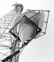 | 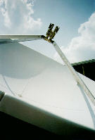 |
| CH-10 Conical Horn (Legacy) | Antenna with Dual Beam Feed |
| Antenna Web Pages |
|
Return to Table of ContentsReturn to AFC Home Page.
 Antenna Feeds and Microwave Components
|
| Web Pages for Microwave Components, Antenna Feeds, Multi-Satellite and Dual Beam Feeds |
|
Return to Table of ContentsReturn to AFC Home Page.
 Radomes
|
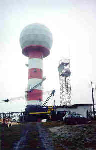
| 12.5 m (41 ft.) Diameter Impedance Matched Radome for S-Band Radar. |
Radome transmission loss is composed of the insertion loss from the RF signal passing through the radome wall and from the scattering loss off the panel flange framework. In most cases, the scattering loss from the framework is several times greater than the wall insertion loss. To reduce scattering loss, AFC engineers use a technique known as impedance matching to "tune out" framework loss. As required by sophisticated electrical performance requirements, circuit elements may be laminated into the dielectric flanges to impedance match scattering loss. Any of the four DSF radome types may be impedance matched. Please refer to the Radome Network Home Page for more information on impedance matched radomes.
- The four DSF radome types are:
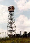
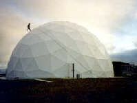
| Thin Membrane | Solid Laminate | 2-Layer Sandwich | 3-Layer Sandwich |
 |
 |
 |
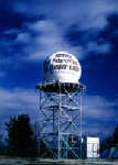 |
| The thin membrane wall DSF radome where adjacent panel flanges carry all the environmental loads. | The solid laminate wall DSF radome. | Adding a layer of foam to the inside thin membrane wall DSF radome forms a 2-layer sandwich wall radome. Foam thickness is chosen primarily for thermal insulation and cost objectives. | The composite 3-layer sandwich foam core wall radome. |
AFC engineers have developed a family of dielectric space frame radomes based on a range of required radome diameters. A set of radomes within a given range of radii will have identical panel count, panel shape and overall geometric layout. Individual panel size and the flange angles, which are radius dependent, will differ to accommodate the radome's overall shape factors. Spherical truncation is also radome specific, and is accommodated by sub panels unique to each requirement. This process of engineering complex designs from the macro point of view has greatly simplified the structural design phase. Emphasis is placed on meeting the material strength requirements of the environmental specifications and of the important electromagnetic constraints as opposed to continually reinventing the radome. To enhance RF performance, a design-balancing process occurs between a stronger structure at maximum rated wind speed and improved RF performance. This balancing act determines that our radomes are designed with appropriate structural safety factors for the lifetime of the radome. It is for this reason that AFC defines radome structural safety by a criterion based on the geometric deformation of the radome shell, which leads to a catastrophic failure wind speed.
Radome accessories customize a radome to suit particular requirements. Accessories may include lightning protection, obstruction lights, ventilation, base collar, personnel door, indoor lights and power kits, hydrophobic coating and impedance matching. For more information, visit AFC's Dielectric Radome data sheets, Radome Capability. and other data sheets summarized below.
| Radome Web Pages |
|
Return to Table of ContentsReturn to AFC Home Page.
 Tallguide ®
|
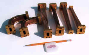
| Tallguide TG31 for 33 to 55 GHz. TG31 replaces WR22 waveguide. |
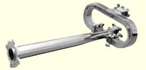
Typical applications are satellite uplinks and radar. For example, the ASDE 3 short pulse airport surveillance radar, uses Tallguide at most major airports within the US, Canada and Europe. Often, ASDE 3 Tallguide runs are several hundred feet long. For satellite communications applications, Tallguide increases uplink power --- significantly reducing earth station cost. For further satellite communications data, see How to Combat Uplink Power Loss reprinted from the January 1995 issue of Satellite Communications.
Specific Tallguide component design information for Tallguide frequency bands may be found at the Tallguide Home Page, which is the starting point for all Tallguide information.
| 5.8 - 7.0 GHz | 7 - 10 GHz | 8.2 - 12.4 GHz | 10 - 15 GHz | 12 - 20 GHz | 15 - 22 GHz | 17 - 27 GHz | 22 - 33 GHz | 26 - 40 GHz | 33 - 55 GHz | 50 - 75 GHz | 60 - 90 GHz | 75 - 110 GHz |
| WR137 | WR112 | WR90 | WR75 | WR62 | WR51 | WR42 | WR34 | WR28 | WR22 | WR15 | WR12 | WR10 |
| TG215 | TG170 | TG134 | TG115 | TG87 | TG80 | TG62 | TG50 | TG40 | TG31 | TG23 | TG17 | TG16 |
| Tallguide Home Page | Tallguide Data Sheet | How to Combat Uplink Power Loss | ||||||||||
Return to Table of ContentsReturn to AFC Home Page.
AFC manufactures custom shelters to solve a variety of needs. Typical examples are transportable uplinks and secure airborne deliverable shelter modules. In todays tactical, highly mobile atmosphere, shelters often encompass dual use roles. Such tactical applications include an airborne deployed environmentally controlled 8x8x20 foot shelter housing a complete 26 foot diameter radome. Accessories and optional features may include TEMPEST design, personnel and equipment doors, alarm and emergency systems. |
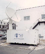 |
and Antenna System |
Return to Table of ContentsReturn to AFC Home Page.
 The Company
Antennas for Communications was founded by Steven Galagan and Howard Hubbard on February 2, 1972. Microdyne Corporation purchased AFC in 1979 and operated the business as a wholly owned subsidiary with its own banking, accounting and engineering. Following Microdyne's merger with Federal Technology, in June 1991 an AFC employee group purchased the assets of AFC from Microdyne. In July 2011, AFC moved into new 40,000 Sq-ft facilities. Operations and manufacturing quality control are certified under ISO 9001 : 2015. AFC is a privately held Florida corporation registered on SAM.GOV.
AFC's headquarters are in Ocala, Florida, which is located 1-1/2 hours north of Orlando. From Orlando international airport, take the Florida Turn Pike north to Highway 75. Florida Map Orlando to Ocala.
A complete Internet WWW AFC document index may be found in Antennas for Communications (AFC) Home Page Document Summary List.
Return to Table of Contents    Return to AFC Home Page.
    AFC Page Browser
Telephone (352) 687-4121 Fax (352) 687-1203 E-mail sales@afcsat.com
Tallguide is a Registered Trademark of Antennas for Communications
Copyright © 1996 - 2017 Antennas for Communications
